Air2O

Air2O

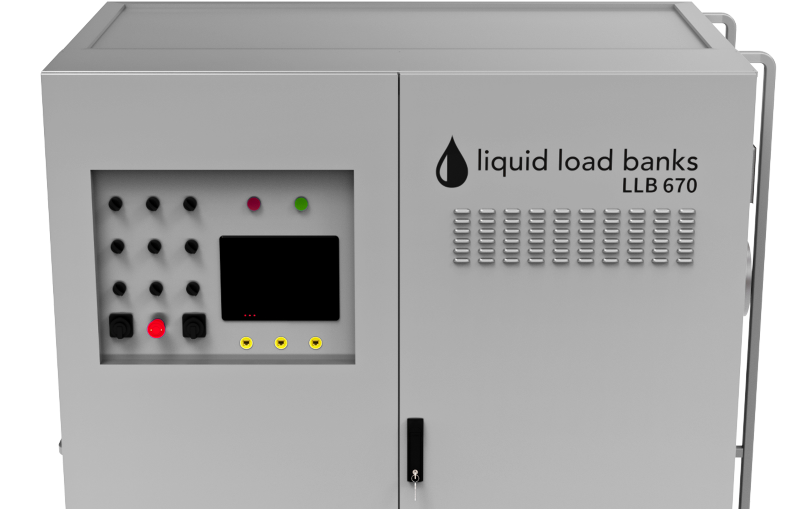
LLB 670

Product Hero — Air2O

LIQUID LOAD
BANK

Revolutionizing Commissioning
for Liquid Load Banks

CRAH product

Delivering comprehensive test solutions for mission-critical data centers in the AI era.

Offered in partnership with Liquid Load Banks, this next-generation load bank is engineered to validate high-density compute infrastructure by rigorously testing electrical and mechanical systems in new mission-critical facilities. Manufactured by Air2O using Liquid Load Banks’ patent-pending design, it supports 500kW at 415V and up to 670kW at 480V—delivering robust, reliable, and repeatable performance for commissioning data centers and other critical environments.
“This partnership is built on exceptional engineering and a profound belief in each other’s respective areas of expertise,” said Sullivan. “Data center operators are assured of a comprehensive cooling and testing solution manufactured to the highest standards, helping them expand their capabilities for the AI era.”
Download Spec Sheet

Liquid-Cooled Load Bank for Thermal Commissioning

The LLB 670 is a liquid-cooled resistive load bank that applies a controlled thermal load to coolant loops, coolant distribution units, chillers, and heat rejection equipment. It delivers up to 670 kW in steps as fine as 6.7 kW while holding flow and outlet temperature steady, for commissioning, acceptance testing, and performance verification.

670 kW in 6.7 kW Steps

Nine switchable heater stages apply up to 670 kW at 480 V, or 500 kW at 415 V, to the liquid loop under test. Load is set in steps as fine as 6.7 kW, about 1% of rated capacity, for controlled ramping during commissioning.

  • 670 kW and 806 A at 480 V
  • 500 kW and 697 A at 415 V
  • Nine stages, 6.7 kW minimum step
  • Rated capacity within ±2%

Basis: Rated capacity at 480 V and at 415 V nominal supply. Rated capacity, flow range, and temperature limits are not concurrent operating points, and ratings at the test conditions are confirmed on the design datasheet Air2O issues for each project.

Flow and Outlet Temperature Held Steady

A 316 stainless steel V-port modulating valve and an ultrasonic flow meter hold loop flow and outlet temperature steady for repeatable test conditions. A built-in three-phase power meter with current transformers reports real power and load current throughout the test.

  • 316 stainless V-port valve, 0 to 100% control
  • Ultrasonic flow measurement
  • Flow range 0.75 to 3.0 LPM/kW
  • Design flow 1.5 LPM/kW

Basis: Flow in liters per minute per kW of applied load (LPM/kW). Design flow at 670 kW is about 1,005 LPM (265 gpm). Rated capacity, flow range, and temperature limits are not concurrent operating points.

Mobile Cabinet and Loop Connection

The unit connects to the loop under test through 3 in. ASME B16.5 flanges and takes power on twelve 400 A camlocks, four per phase. The cabinet moves on casters or by forklift, and the advanced package adds a weatherproof enclosure and sequential chaining for tests above 670 kW.

  • 70 x 46 x 85 in. cabinet
  • 25% propylene glycol (PG25) working fluid
  • Inlet up to 122°F, outlet up to 158°F
  • 100 psi maximum working pressure

Basis: Cabinet size given as length x width x height. Estimated weight is 3,200 lb dry and 3,750 lb filled, within ±10%. Rated capacity, flow range, and temperature limits are not concurrent operating points.

Touchscreen Operation and DDC Control

A 10.1 in. touchscreen provides stage control, live telemetry, and alarms, backed by hard-wired stage switches. A native BACnet DDC controller runs the unit standalone, and the advanced package adds BACnet and Modbus integration and remote monitoring through the building management system.

  • Native BACnet DDC controller
  • 10.1 in. touchscreen, hard-wired stage switches
  • Two Ethernet ports, USB, and unit chain port
  • BMS integration in the advanced package

ASME Vessel With Layered Protection

The heating vessel is built to ASME Section VIII Division 1 with a U stamp and National Board registration, in acid-washed and passivated 316L stainless steel. The load bank is protected by a pressure relief valve, high-pressure and high-temperature switches, an emergency stop, and dedicated fault relays.

  • ASME Section VIII Division 1, U stamp
  • 316L vessel, PMI verified
  • Pressure relief valve and safety switches
  • 20-year vessel design life
Committed To Innovation Sustainability and Energy Efficency